|
CGAL 6.1 - 2D Conforming Triangulations and Meshes
|
|
CGAL 6.1 - 2D Conforming Triangulations and Meshes
|
This package implements Shewchuk's algorithm [1] to construct conforming triangulations and 2D meshes. Conforming triangulations will be described in Section Conforming Triangulations and meshes in Section Meshes.
A triangulation is a Delaunay triangulation if the circumscribing circle of any facet of the triangulation contains no vertex in its interior. A constrained Delaunay triangulation is a constrained triangulation which is as much Delaunay as possible. The circumscribing circle of any facet of a constrained Delaunay triangulation contains in its interior no data point visible from the facet.
An edge is said to be a Delaunay edge if it is inscribed in an empty circle (containing no data point in its interior). This edge is said to be a Gabriel edge if its diametrical circle is empty.
A constrained Delaunay triangulation is said to be a conforming Delaunay triangulation if every constrained edge is a Delaunay edge. Because any edge in a constrained Delaunay triangulation is either a Delaunay edge or a constrained edge, a conforming Delaunay triangulation is in fact a Delaunay triangulation. The only difference is that some of the edges are marked as constrained edges.
A constrained Delaunay triangulation is said to be a conforming Gabriel triangulation if every constrained edge is a Gabriel edge. The Gabriel property is stronger than the Delaunay property and each Gabriel edge is a Delaunay edge. Conforming Gabriel triangulations are thus also conforming Delaunay triangulations.
Any constrained Delaunay triangulation can be refined into a conforming Delaunay triangulation or into a conforming Gabriel triangulation by adding vertices, called Steiner vertices, on constrained edges until they are decomposed into subconstraints small enough to be Delaunay or Gabriel edges.
Constrained Delaunay triangulations can be refined into conforming triangulations by the two following global functions:
In both cases, the template parameter CDT must be instantiated by a constrained Delaunay triangulation class (see Chapter 2D Triangulations).
The geometric traits of the constrained Delaunay triangulation used to instantiate the parameter CDT has to be a model of the concept ConformingDelaunayTriangulationTraits_2.
The constrained Delaunay triangulation t is passed by reference and is refined into a conforming Delaunay triangulation or into a conforming Gabriel triangulation by adding vertices. The user is advised to make a copy of the input triangulation in the case where the original triangulation has to be preserved for other computations
The algorithm used by make_conforming_Delaunay_2() and make_conforming_Gabriel_2() builds internal data structures that would be computed twice if the two functions are called consecutively on the same triangulation. In order to avoid these data to be constructed twice, the advanced user can use the class Triangulation_conformer_2<CDT> to refine a constrained Delaunay triangulation into a conforming Delaunay triangulation and then into a conforming Gabriel triangulation. For additional control of the refinement algorithm, this class also provides separate functions to insert one Steiner point at a time.
This example inserts several segments into a constrained Delaunay triangulation, makes it conforming Delaunay, and then conforming Gabriel. At each step, the number of vertices of the triangulation is printed.
See Figure 56.1

Figure 56.1 From left to right: Initial Delaunay triangulation, the corresponding conforming Delaunay, and the corresponding Gabriel triangulation.
A mesh is a partition of a given region into simplices whose shapes and sizes satisfy several criteria.
The domain is the region that the user wants to mesh. It has to be a bounded region of the plane. The domain is defined by a planar straight line graph, Pslg for short, which is a set of segments such that two segments in the set are either disjoint or share an endpoint. The segments of the Pslg are constraints that will be represented by a union of edges in the mesh. The Pslg can also contain isolated points that will appear as vertices of the mesh.
The segments of the Pslg are either segments of the boundary or internals constraints. The segments of the Pslg have to cover the boundary of the domain.
The Pslg divides the plane into several connected components. By default, the domain is the union of the bounded connected components.
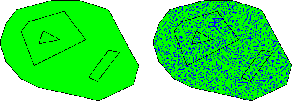
See Figure 56.2 for an example of a domain defined without using seed points, and a possible mesh of it.

Figure 56.2 A domain defined without seed points and the generated mesh.
The user can override this default by providing a set of seed points. Either seed points mark components to be meshed or they mark components not to be meshed (holes).
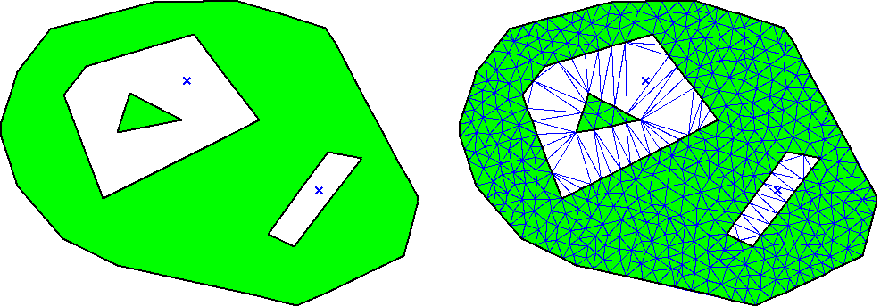
See Figure 56.3 for another domain defined with the same Pslg and two seed points used to define holes. In the corresponding mesh these two holes are triangulated but not meshed.

Figure 56.3 A domain with two seeds points defining holes and the generated mesh.
The shape criterion for triangles is a lower bound \( B\) on the ratio between the circumradius and the shortest edge length. Such a bound implies a lower bound of \( \arcsin{\frac{1}{2B}}\) on the minimum angle of the triangle and an upper bound of \( \pi - 2* \arcsin{\frac{1}{2B}}\) on the maximum angle. Unfortunately, the termination of the algorithm is guaranteed only if \( B \ge \sqrt{2}\), which corresponds to a lower bound of \( 20.7\) degrees over the angles.
The size criterion can be any criterion that tends to prefer small triangles. For example, the size criterion can be an upper bound on the length of longest edge of triangles, or an upper bound on the radius of the circumcircle. The size bound can vary over the domain. For example, the size criterion could impose a small size for the triangles intersecting a given line.
Both types of criteria are defined in an object criteria passed as parameter of the meshing functions.
The input to a meshing problem is a Pslg and a set of seeds describing the domain to be meshed, and a set of size and shape criteria. The algorithm implemented in this package starts with a constrained Delaunay triangulation of the input Pslg and produces a mesh using the Delaunay refinement method. This method inserts new vertices to the triangulation, as far as possible from other vertices, and stops when the criteria are satisfied.
If all angles between incident segments of the input Pslg are greater than \( 60\) degrees and if the bound on the circumradius/edge ratio is greater than \( \sqrt{2}\), the algorithm is guaranteed to terminate with a mesh satisfying the size and shape criteria.
If some input angles are smaller than \( 60\) degrees, the algorithm will end up with a mesh in which some triangles violate the criteria near small input angles. This is unavoidable since small angles formed by input segments cannot be suppressed. Furthermore, it has been shown ([1]), that some domains with small input angles cannot be meshed with angles even smaller than the small input angles. Note that if the domain is a polygonal region, the resulting mesh will satisfy size and shape criteria except for the small input angles. In addition, the algorithm may succeed in producing meshes with a lower angle bound greater than \( 20.7\) degrees, but there is no such guarantee.
Meshes are obtained from constrained Delaunay triangulations by calling the global function:
The template parameter CDT must be instantiated by a constrained Delaunay triangulation class.
The geometric traits class of CDT has to be a model of the concept DelaunayMeshTraits_2. This concept refines the concept ConformingDelaunayTriangulationTraits_2 adding the geometric predicates and constructors.
The second template parameter NamedParameters enables to pass a sequence of seed points to define a domain. It further enables to pass meshing criteria that the triangles have to satisfy. The criteria must be a model of MeshingCriteria_2.
CGAL provides two models for this concept:
Delaunay_mesh_criteria_2<CDT>, that defines a shape criterion that bounds the minimum angle of triangles, Delaunay_mesh_size_criteria_2<CDT>, that adds to the previous criterion a bound on the maximum edge length. If the function refine_Delaunay_mesh_2() is called several times on the same triangulation with different criteria, the algorithm rebuilds the internal data structure used for meshing at every call. In order to avoid rebuild the data structure at every call, the advanced user can use the class Delaunay_mesher_2<CDT>. This class provides also step by step functions. Those functions insert one vertex at a time.
Any object of type Delaunay_mesher_2<CDT> is constructed from a reference to a CDT, and has several member functions to define the domain to be meshed and to mesh the CDT. See the example given below and the reference manual for details. Note that the CDT should not be externally modified during the life time of the Delaunay_mesher_2<CDT> object.
Once the mesh is constructed, one can determine which faces of the triangulation are in the mesh domain using the is_in_domain() member function of the face type (see the concept DelaunayMeshFaceBase_2).
The package also provides a global function that runs Lloyd optimization iterations on the mesh generated by Delaunay refinement. The goal of this mesh optimization is to improve the angles inside the mesh, and make them as close as possible to 60 degrees.
Note that this global function has several named parameters (see details in reference pages) to tune the optimization process.
This optimization process alternates relocating vertices to the center of mass of their Voronoi cells, and updating the Delaunay connectivity of the triangulation. The center of mass is computed with respect to a sizing function that was designed to preserve the local density of points in the mesh generated by Delaunay refinement.
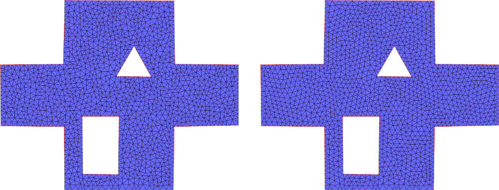
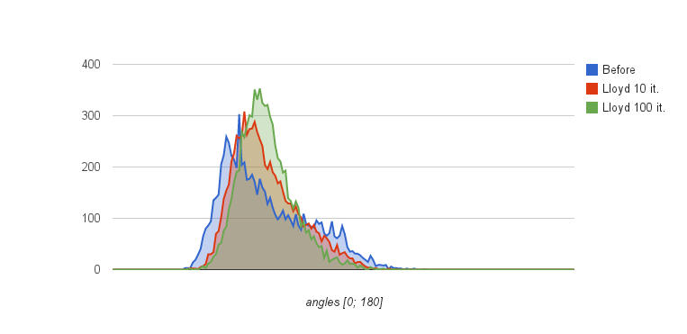
See Figure Figure 56.4 for a mesh generated by refine_Delaunay_mesh_2() and optimized with lloyd_optimize_mesh_2(). Figure Figure 56.5 shows the histogram of angles inside these meshes.

Figure 56.4 (Left) Mesh generated by refine_Delaunay_mesh_2() for a uniform sizing criterion. (Right) shows the same mesh after 100 iterations of Lloyd optimization.

Figure 56.5 Histograms of angles inside the mesh after Delaunay refinement, and after 10 and 100 iterations of Lloyd optimization. After Delaunay refinement, angles are in the interval [28.5; 121.9] degrees. After 10 iterations of Lloyd optimization, they are in [29.1; 110.8]. 100 iterations take them to [29.3; 109.9].
As of CGAL 5.6, lloyd_optimize_mesh_2() uses Named Parameters to set parameters. More details are provided in Upgrading Code using Boost Parameters to CGAL Named Function Parameters.
The following example inserts several segments into a constrained triangulation and then meshes it using the global function refine_Delaunay_mesh_2(). The size and shape criteria are the default ones provided by the criteria class Delaunay_mesh_criteria_2<K>. No seeds are given, meaning that the mesh domain covers the whole plane except the unbounded component.
This example uses the class Delaunay_mesher_2<CDT> and calls the refine_mesh() member function twice, changing the size and shape criteria in between. In such a case, using twice the global function refine_Delaunay_mesh_2() would be less efficient, because some internal structures needed by the algorithm would be built twice.
This example uses the global function refine_Delaunay_mesh_2() but defines a domain by using one seed. The size and shape criteria are the default ones provided by the criteria class Delaunay_mesh_criteria_2<K>.
Once the mesh is constructed, the is_in_domain() member function of faces is used to count them.
File Mesh_2/mesh_with_seeds.cpp
When the domain is defined by polygons for the outer boundaries and the boundaries of holes the function mark_domain_in_triangulation() can be called instead of passing seedpoints.
File Mesh_2/mesh_marked_domain.cpp
This example uses the global function lloyd_optimize_mesh_2(). The mesh is generated using the function refine_Delaunay_mesh_2() of CGAL::Delaunay_mesher_2, and is then optimized using lloyd_optimize_mesh_2(). The optimization will stop after 10 (set by max_iteration_number) iterations of alternating vertex relocations and Delaunay connectivity updates. More termination conditions can be used and are detailed in the Reference Manual.
File Mesh_2/mesh_optimization.cpp
It is possible to export the result of a meshing in VTU, using the function CGAL::IO::write_VTU(). For more information about this format, see VTK (VTU / VTP / legacy) File Formats.